
Whether an end user is loading a webpage, joining a video conference, or picking up a classic landline, the experience depends on one critical piece of engineering: the access network (the “last mile”).
Over the decades, telecom architecture has undergone a radical transformation. We transitioned from massive, high-maintenance copper distribution frames running analog audio loops to passive optical splitters pushing multiple gigabits over strands of glass.
Let’s unpack how traditional copper topologies work, why digital loop carriers and remote MSANs were introduced, and how modern FTTC and GPON/FTTH networks superseded them.
1. The Classical Copper Hierarchy: Inside the Main Distribution Frame (MDF)
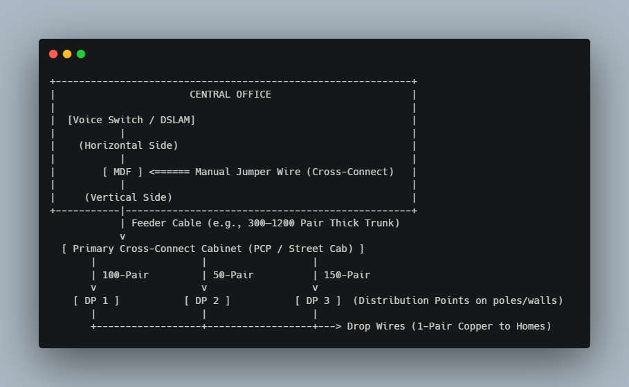
In traditional plain old telephone service (POTS) and early xDSL architectures, the Central Office (CO) or Telephone Exchange serves as the primary gateway. At its core sits the Main Distribution Frame (MDF).
The Anatomy of an MDF
The MDF is a giant, two-sided mechanical interconnection rack:
- The Horizontal Side (Equipment Side): Terminates the internal lines connected to line cards, voice switching matrices, and DSLAMs (Digital Subscriber Line Access Multiplexers).
- The Vertical Side (Line/Outside Plant Side): Terminates the heavy underground feeder cables arriving from the outside streets via the cable vault.
- The Jumper: To provision or alter a subscriber’s service, an engineer manually runs a twisted jumper wire between specific pins on the equipment side and specific cable pairs on the line side.
Primary vs. Secondary Copper Distribution
- Primary Feeder Network (High Capacity, Low Local Spread): Heavy-gauge multi-pair cables (e.g., 300, 600, or 1200 pairs) exit the exchange. These cables concentrate huge transmission capacity into high-density arterial routes.
- The Street Cabinet (Cross-Connection Point): The primary feeder terminates at a passive street cabinet. Inside, heavy trunks split into smaller distribution cables.
- Secondary Distribution Network (Lower Capacity, Broad Footprint): Cables with lower pair counts (e.g., 50, 100, or 150 pairs) radiate from the street cabinet to poles or street-level Distribution Points (DPs).
- Drop Cable: A lightweight 1- or 2-pair drop wire runs directly into the customer premises.
The Trade-off: Primary lines prioritize capacity and aggregation, while secondary lines prioritize geographic footprint and reach. However, every mechanical joint, splice, and terminal box introduces signal attenuation, cross-talk, and ingress noise.
2. Moving Digital Closer to the Curb: DLC and MSAN Deployments
As subscriber clusters grew further away from central exchanges, physics became an insurmountable problem. High-frequency signals like ADSL2+ suffer rapid attenuation over long copper loops.
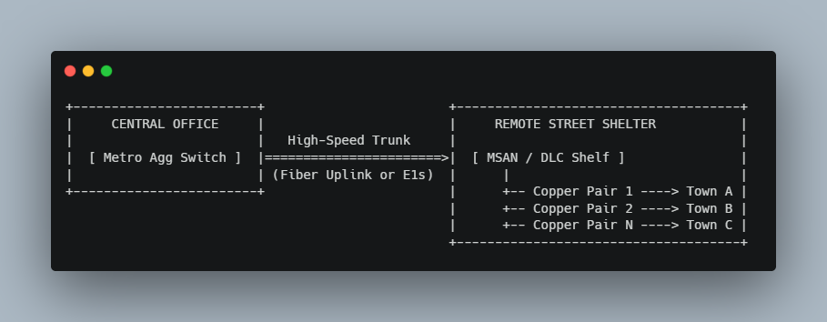
To solve loop-length limitations, telecom operators introduced Digital Loop Carriers (DLC) and Multi-Service Access Nodes/Gateways (MSAN/MSAG).
How Remote DLCs Work
Instead of running hundreds of analog copper lines miles across town from the exchange:
- The operator deploys a powered outdoor enclosure (or mini-shelter) near the neighborhood.
- High-speed backhaul connects the Central Office to the remote site (historically via multiplexed E1 links @ 2.048 Mbps running over G.703/SDH, and later over 1G/10G Ethernet optical uplinks).
- The remote DLC/MSAN houses line cards directly in the neighborhood, shortening the copper loop to just a few hundred meters. This localized distribution drastically cuts noise and delivers higher xDSL data rates (like VDSL2).
3. The Hybrid Era: Fiber-to-the-Cabinet (FTTC) & VDSL
FTTC (Fiber to the Cabinet) represents the evolutionary bridge between full copper and full fiber
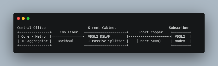
- Backhaul: Single-mode fiber extends from the Central Office to the roadside cabinet.
- Node Processing: An active cabinet housing a compact DSLAM converts optical Ethernet traffic into VDSL2 signals.
- Last Mile: The existing legacy twisted-pair copper drop carries the signal the remaining 100 to 500 meters into the premises.
- Result: While FTTC avoids the cost of digging up every private driveway to lay fiber, it remains constrained by copper degradation, RF interference, and cabinet power requirements.
4. The Modern Standard: GPON and FTTH (Fiber-to-the-Home)
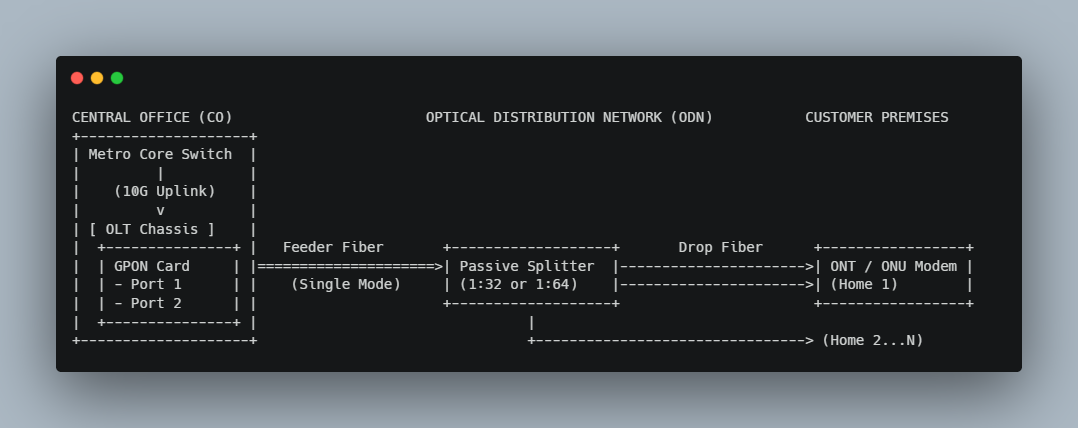
In FTTH (Fiber to the Home), copper is eliminated entirely from the distribution path. The dominant architecture powering modern FTTH is Gigabit Passive Optical Network (GPON).
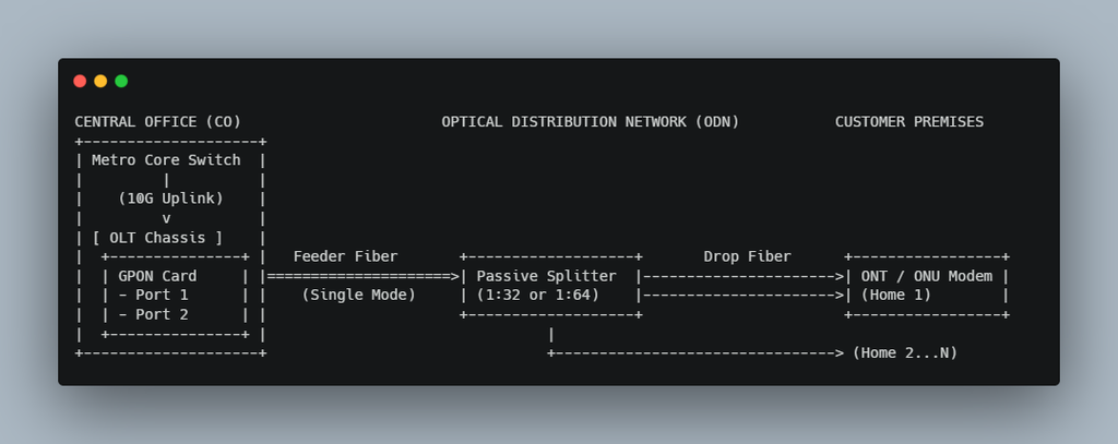
Unlike legacy active networks, GPON uses point-to-multipoint (P2MP) optical distribution with zero active electronics between the exchange and the home.
Core Components of GPON
- OLT (Optical Line Terminal): Located at the exchange/headend, the OLT converts IP traffic from the metro aggregator into downstream optical frames and arbitrates upstream traffic from subscribers.
- ODN (Optical Distribution Network): The completely passive physical infrastructure consisting of single-mode fiber cables, optical distribution frames (ODF), splice enclosures, and optical splitters.
- Passive Optical Splitters: Optical prisms that split a single incoming light beam into multiple separate fibers without requiring electricity. Common split ratios include 1:32 or 1:64 (and sometimes tiered, e.g., a 1:4 primary split followed by a 1:16 secondary split).
- ONT / ONU (Optical Network Terminal / Unit): The customer-premises device that terminates the fiber and translates optical wavelengths into standard Ethernet and Wi-Fi signals.
GPON Transmission Fundamentals
GPON operates across single strands of single-mode fiber using Wavelength Division Multiplexing (WDM):
| Direction | Wavelength | Standard Rate | Multiplexing Technique |
| Downstream (OLT $\to$ ONT) | 1490 nm | 2.488 Gbps | TDM (Time-Division Multiplexing): Continuous broadcast; each ONT extracts its own packets via GEM (GPON Encapsulation Method) headers. |
| Upstream (ONT $\to$ OLT) | 1310 nm | 1.244 Gbps | TDMA (Time-Division Multiple Access): Burst mode; the OLT assigns dynamic, dedicated time slots to prevent laser collision. |
| RF Video Overlay (Optional) | 1550 nm | N/A | Dedicated broadcast downstream for analog/digital TV signals. |
Architectural Summary: The Generational Evolution
| Characteristic | Legacy Copper (MDF) | Digital Loop Carrier (DLC/MSAN) | FTTC (VDSL2) | FTTH (GPON) |
| Primary Medium | Twisted Copper Pairs | Fiber / High-Capacity Copper + Local Copper Loop | Fiber to Cabinet + Copper Drop | 100% Single-Mode Optical Fiber |
| Field Electronics | Fully Passive (Static wiring) | Active (Heated/cooled remote field shelters) | Active (Street cabinet requires local power) | Fully Passive Outside Plant (Zero power between CO and ONT) |
| Typical Bandwidth | Up to 56 Kbps (Analog) / 24 Mbps (ADSL2+) | Up to 24–50 Mbps | Up to 100–300 Mbps | 1 Gbps – 2.5 Gbps (XGS-PON pushes to 10 Gbps) |
| Max Reach | ~3–5 km (Heavy degradation past 2 km) | ~1–2 km from MSAN | < 500 m on copper leg | Up to 20 km optical budget |
| Failure Points | Moisture, oxidation, cross-talk, bridge taps | Power failure, line-card faults, short copper loop issues | Cabinet power, thermal limits, copper noise | Optical bends, dirty fiber end-faces, macrobends |
Key Takeaway
The migration from copper MDFs to fiber GPON represents a shift from high-maintenance, distance-limited electrical circuits to low-attenuation, passive photonic networks. By replacing copper trunks and active roadside repeaters with passive splitters and high-density OLTs, modern networks lower operational overhead while delivering practically limitless line-rate upgrades simply by swapping transceivers at either end.